
IMAGE INSTRUCTIONS ARE GIVEN THROUGHOUT THE TEXT - I don't have captions yet but if you could leave space for them please.
IMAGE 508 NEAR BEGINNING
Heat, oil and particularly a combination of the two, don’t prolong the lifespan of copper cored electrical wire. An old forestry machine will have long lengths of electrical cabling that is blighted by cracked insulation and core wire that’s been turned black by corrosion. All of this adds up to bad connections where there should be good connections, and connections where there shouldn’t be connections – these are usually direct to earth and result in fuses popping or wires melting. Whatever the symptoms, the effects are generally a load of functions that don’t, and others that do when you don’t want them to!
We felled a steep bank on a private estate a few years ago and I couldn’t find a full-time faller who could do the whole job so I took on the bulk of the felling and put a driver in the 250 I usually used. He came to me one day and said that there was a problem with the drive on the 250. It would stop driving momentarily, then it would set off again, sometimes in the opposite direction. That particular 250 was one we had fitted a later turbocharged engine and heavier pumps from an FMG 250 into, and I did recall thinking the main wiring loom under the transmission looked quite vulnerable as it was lying on top of the fuel tank. So, I thought that would be a good place to start. I went to work on the Saturday morning and there it was, a bundle of bare wires. All the wires at the bottom of the loom had been rubbing on the top of the diesel tank which was polished bright. The lower half of the loom looked like it had been rubbed flat with a belt sander but at least the wire looked in good condition, probably because it had been soaked in hydraulic oil for a long time. It took me four hours to cut out and replace all the naked wires with new, although I have to admit I replaced everything with the only two colours of wire I had. I did wrap the entire loom in new loom tape and fitted two layers of ribbed conduit before using hose wrap to finish it all off. To my amazement, it worked faultlessly for the remainder of the time I had it and as far as I know it’s still working today.
It might be obvious from my tone that I’m much happier doing any repairs other than electrical ones but with an old machine like this there’s little choice but to tackle the electrical issues head on. It doesn’t take much to have a machine stopped and useless due to a single wiring fault.
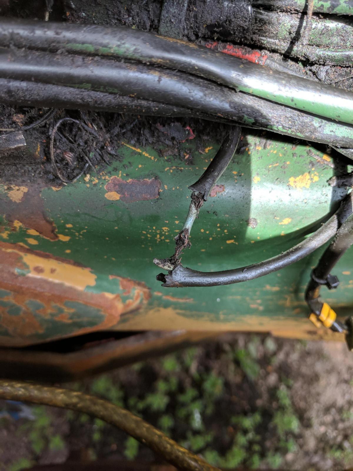
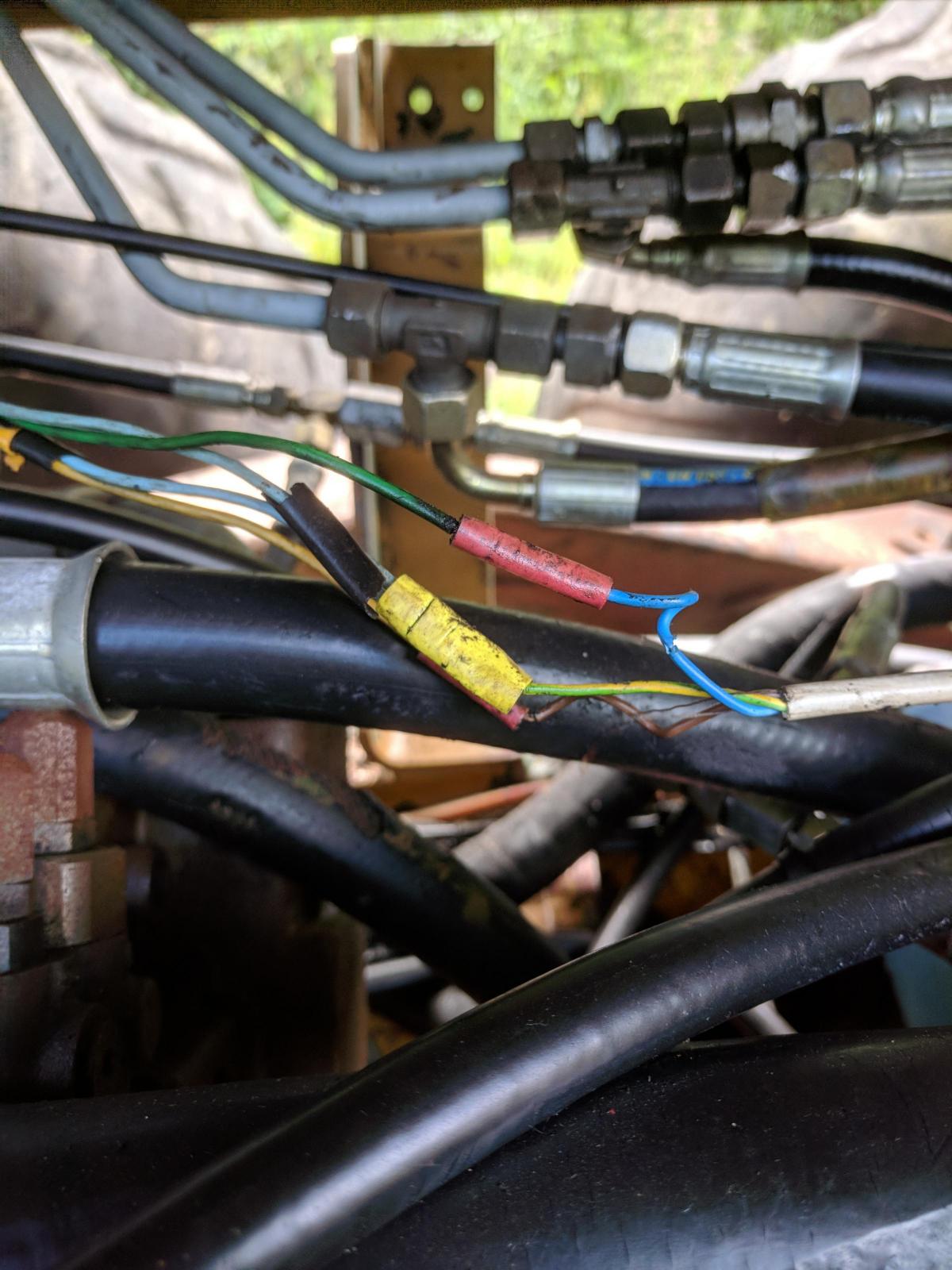
The first thing to do is a thorough inspection of the wiring with a view to spotting any obvious breaks, bad connections or bare wires. One thing that often crops up with old machinery is wires that have been cut off and left uninsulated. It doesn’t take a minute to pop an insulated crimp on the end of any wires that have been cut off but it’s often ignored. A quick way to find where problems are is to fit all new fuses and see what pops. The stop solenoid, fuel gauge and the horn were immediate casualties so that was where we started.
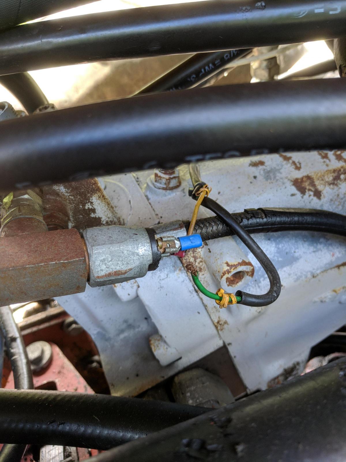
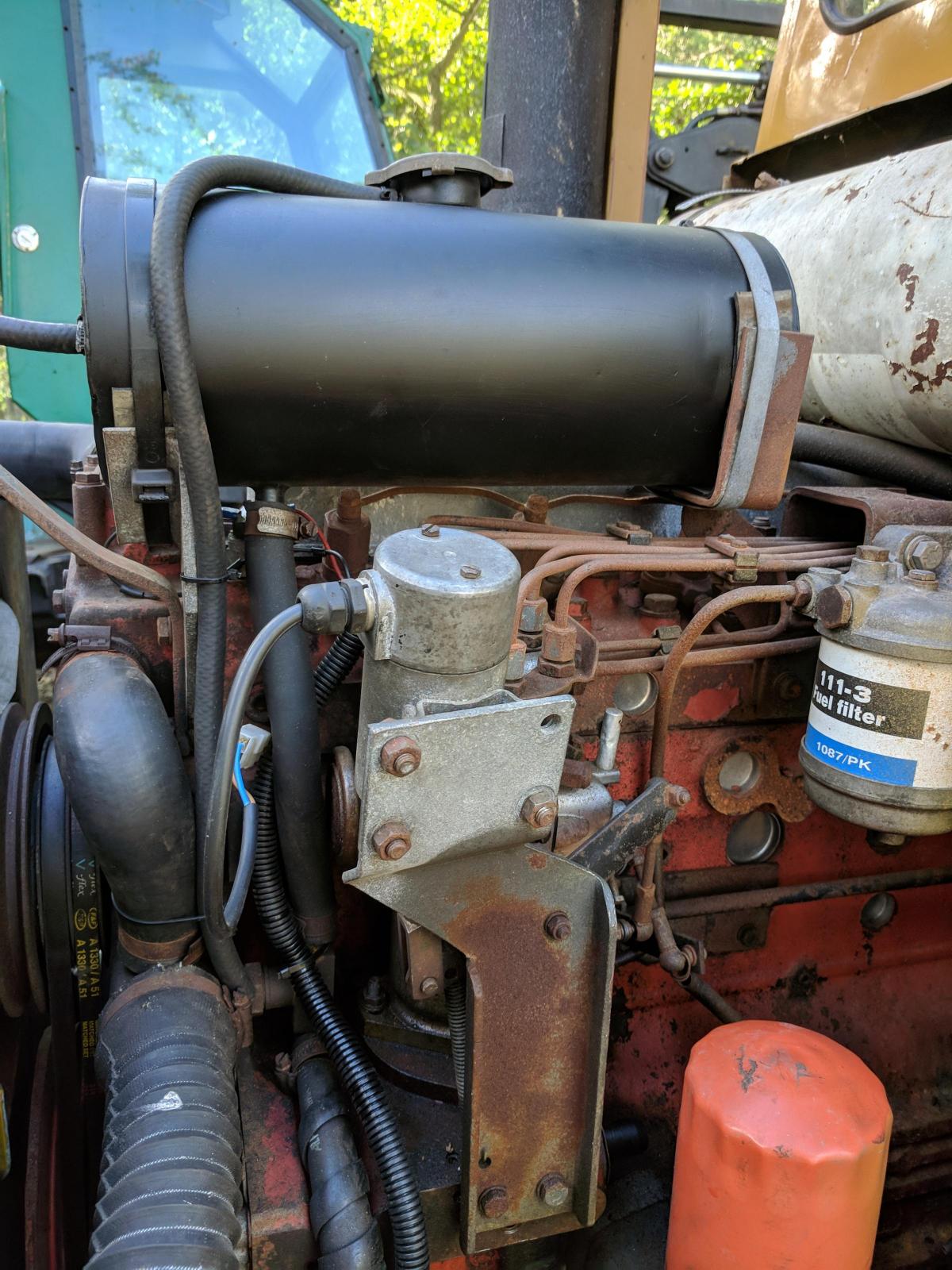
The stop solenoid is pretty simple in operation; it pulls with a supply and releases when the supply is removed so any major electrical fault will stop the engine. The solenoid on this one was held in the pulled position by a strong spring so the engine ran but didn’t stop on the key. The fuse blew immediately it was replaced and the ignition was turned on. We removed the solenoid, stripped it down, replaced the dodgy cabling and wired it across the batteries where it worked perfectly. Refitting the cover and plugging it back in it again blew the fuse when the ignition was turned on. With a multimeter across the wiring we found both connections went straight to earth, and on careful inspection we discovered a diode that didn’t seem necessary. Diodes are basically one-way valves that let power flow one way in a cable. They’re generally used when a supply can’t be allowed to flow back along a cable, usually when two functions are being triggered by the same circuit. The diode on the stop solenoid looked like it had been fitted to stop the live running straight to earth but it was the diode that was causing the short as one of its connecting wires was touching the solenoid’s metal cap. Removing the diode cured the fault and refitting a more suitable spring in the correct position had the solenoid functioning properly with the engine starting and stopping on the key.
The fuel gauge was more complicated – it had a broken wire that was going to earth via the chassis. With this repaired and a fuse fitted, there was no more issue other than that it didn’t work. A good look at the sender unit soon had the answer. The fuel pickup and the tank returns all go through a block on the tank just behind the far side front cab panel. The pickup pipe has a banjo fitting onto this block where the fuel has to turn a right angle through the fitting – a notorious point where blockages occur. It’s almost routine on 250 forwarders to remove the banjo and knock the needles and dead insects out of the hollow banjo bolt. I fuel my machines out of grab tanks with filters on the fuelling pump and in the tank fillers of the machines. I haven’t had the same fuel system problems since I stopped fuelling machines from drums.
This has most likely been a problem with this machine at sometime in the past and someone has fitted a pickup pipe into the fuel sender which, while curing the blockage problem, has also left the machine without a fuel gauge. This is something that isn’t acceptable to me; a machine that runs out of fuel unexpectedly can leave an operator in a sticky spot – ask one guy I know who was burning brash when the forwarder ran out whilst he was loading a big fire. The machine got so hot before we could recover it that the windows had started to crack. The only answer is a new sender unit, which might be an issue although I have had some success repairing these units in the past, never permanently though; they do seem to fall into the ‘once it’s broke, it stays broke’ category of electrical components.
IMAGES 050, 116 AND 646 TOGETHER HERE
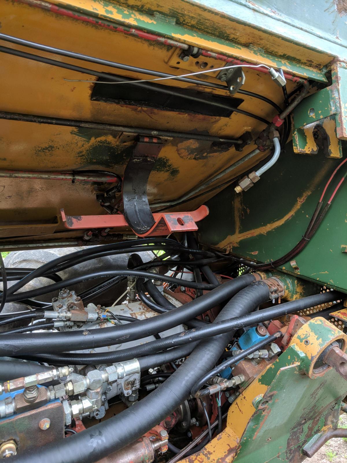
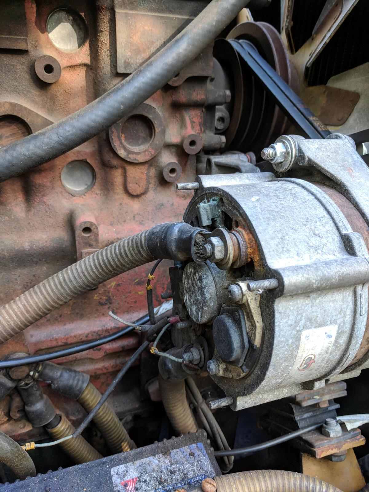
There are two main runs of wiring under the cab and both emanate from the main wiring board in the cab. One runs under the transmission pump then along the door side of the cab supplying the brakes, eight-wheel-drive selector, high/low box etc. The other feeds various sender units and solenoids on the other side of the cab. This is where all the heat- and age-related damage is usually found. This old machine needed a whole load of wiring replacing due to its crispy condition. We also had to add insulated ends to a number of wires which had been clipped off over the years. Some of these we left in situ because among the things that don’t work are the high and low box and the selector to drop the machine out of eight-wheel drive and although having these working just now isn’t essential, the solenoids, actuator valves and all the pipes are still in place so it is something we’ll revisit once we’ve had the machine working for a while.
Once the essential wiring outside the cab had been tidied up, we turned to a whole bunch of wires that look like they’ve been melted at some point. The worst of this is the wiring for the trailer type sockets that would have supplied the lighting boards for road lights when the machine was new. Removing the sockets and all the wiring made space in the wiring loom runs and got rid of more potential trouble spots. Stripping out the wiring for the fire suppression system and the cab night heater freed up more space and tidied up a load of scruffy sub looms. With black conduit fitted over the engine bay wiring it was starting to look tidier around the whole machine but inside the cab needed a lot of attention, especially as we still have a lot of fuse holders with no fuses in.
I can still just about remember what the Swedish script in the wiring and relay legend inside the cover means but a quick look at Google Translate refreshed my memory. Some of it’s easy; ‘katastrofbroms’ is simple to work out – catastrophe brake or emergency brake. What about ‘akdrift’ though? That’s not so easy.
Anyhow, we pulled the main circuit boards and examined them. There were signs of repair where someone had soldered some short wires onto the back of one board to bridge a broken circuit but, other than that, they all looked dirty but sound. A clean with a soft paint brush and a light spray with WD40 was all that was required. Some of the many relays don’t have clips on them, but we’ll sort that. One relay was clearly worse for wear with a large amount of burning on the contacts so that was replaced.
Hoovering the dust, broken glass and screws lost over the years allowed most of the panel to be seen and everything looked in reasonable order. I spent a couple of hours removing a load of redundant wires from the main power rail under the fuses. I’m not even sure what some of them had been used for in the past but once everything was tidied up I called our local mobile auto electrical guy in and let him loose for half a day. Ian went through everything; he made a new wiring harness for the crosscountry steering, cutting out the length of hair dryer flex and replacing it with correct wiring fitted with proper plugs. He located and marked all the other extraneous wiring (the horn wiring was tucked in behind the batteries along with the wires for the headlights in the bonnet). He rewired the starter which had a jury rigged trigger wire straight from the ignition switch instead of through the starter relay – effective, but not a permanent solution which would have caused problems in the future.
Most importantly, he tested the whole system for shorts and for any wiring that was going straight to earth. With a clean bill of health for the main wiring we had to set about the task of rewiring the newly repositioned IPS boxes and the air-sprung, heated seat with its new arms and original levers.
If you read the earlier instalments of this series you’ll recall one of the main problems we identified, along with the wrecked seat, was that the IPS boxes that control the crane functions were located on the rear of the seat frame which meant that the large control cable from the IPS boxes into the main machine wiring was dragged around on the floor every time the seat rotated. This, of course, happens whenever the operator changes from driving the machine to using the crane and it had taken its toll on the wiring as there were a couple of wires strung on the outside of the cable conduit. This big lump of cable originally connected to the bottom of the IPS boxes with a 24 pin plug and socket. What we intended to do was reduce the size of the cable trailing on the cab floor by only having the feeds from the hand controls going through it rather than the feeds from the IPS boxes as it had originally. This meant shortening the heavy cable, which also served to get rid of the length of cracked and worn wiring that had been rubbed and flexed back and forth over many years, and lengthening the hand control wiring with substantial soldered and shrink-wrapped joins.
IMAGES 822 AND 850 WITH THIS SEC TION
I left this project up to Richard, who spent most of a day carefully and methodically working through the whole job. To everyone’s delight the whole system worked perfectly once we fired the machine up. The crane functions, that had been erratic but just about usable, were now completely different with some functions insanely quick to operate. This is likely to be because there were a load of freakish settings on the control cards that were compensating for the state of the wiring. After a few moments setting the ramps on the control cards the crane was far from perfect but was adequate to get a start loading some timber once the crane is completed with the addition of a grab and rotator.
The engine starts and stops, the crane works and, after a brief false start caused by a missing relay, the drive works on front and rear controls. This is always a moment of triumph with an Ösa 250 because while it was the steering amplifier as part of the ‘Ösa System’ that marked these out as exceptional forestry machines, it was also what made them fragile once they became old technology.
I’ve had 250s that didn’t give any trouble at all and I’ve had ones that would simply refuse to drive, in any direction, simply because something had failed in the steering amplifier. This could happen at any time but usually it was when they’d been laid up for a period of time, often just a long weekend.
The steering amplifier used in the Ösa System is a crude form of computer although comparing it to a computer is like comparing a Dab radio to a valve radio (which you had to switch on and wait five minutes for it to warm up before you got any sound), and while it performs a similar function by allowing several actions to work in sequence, it lacks the finesse of more modern control systems. In an early Kockums harvester I had when you moved to the next tree it was a case of pushing the clutch down, engaging drive, letting the brakes off and switching the chassis brake off before letting the clutch up and moving off. Stopping at the next tree required the whole process to be done in reverse, and operating the crane demanded the dexterity of a classical piano player, six levers and two keypads took some handling. In a 250 Ösa the same operation was just pressing one button to select drive and gently on the throttle, to stop, let the throttle off and select neutral. Brakes and chassis lock operated together with the drive switch. It must have seemed like a whole new world.
Unfortunately, the cross country steering I’d been worried about didn’t prove as willing to work as the other controls and after a good hour of checking voltages and earths we came to the conclusion the fault lay in the steering amplifier box. There is a spare among the parts that came with the machine but I’m almost certain it came out of a harvester and in my experience there are subtle differences between the harvester and the forwarder versions. It was an easy decision to make; we simply wired the steering buttons on the hand controls so they bypassed the steering amplifier. The switches are traditional on/off switches so the steering is a bit lively but with a gentle operator they’ll be fine. It might be an idea to restrict the function on the valve block slightly but we’ll see how it goes.
Now the jobs remaining are more heavy-duty. The headboard will require some cutting and welding, the steps that were fabricated to be used while we were doing the repairs will have to be made permanent, I’m not a fan of swinging bits of chain that seem hell bent on taking the skin off the shins of the unwary at every opportunity, so that’ll be a priority. The oil cooler we grafted in is currently held in place by a small ratchet strap and there’s various small covers and paint details to sort out.
The 250 is at last up and running and driving about in the yard now. It’s had new wiper blades, fan belts and radiator hoses and we have sorted a pair of band tracks for the back and some aggressive chains for the front so it’ll be ready for the ash felling that we’re still waiting for a felling licence for.
It’s been a long job sorting this forwarder out, but nowhere nearly as long as it takes the Forestry Commission to issue a felling licence for what looked like a straightforward job even before the wood became infected with Chalara.
I’m just a bit worried that we’ll have the next major project done and dusted before the felling licence arrives. It’s only a short project – fit a new crane base and centre joint and rebuild the engine of my old 1270 Timberjack.
I think we’ll maybe just about get most of it done while we’ve got the good weather, if not it’ll have to be an inside job.


Comments: Our rules
We want our comments to be a lively and valuable part of our community - a place where readers can debate and engage with the most important local issues. The ability to comment on our stories is a privilege, not a right, however, and that privilege may be withdrawn if it is abused or misused.
Please report any comments that break our rules.
Read the rules here